TM-9-2520-234-35 - Page 8 of 323
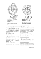
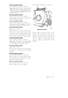
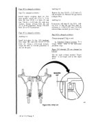
Step u is for XTG 411-2A models. For XTG 411-4
models, install 11 internal and 11 external-splined
brake plates and disks, beginning with an
extemal-splined brake plate (Fig. 174).
Page 128 is changed as follows.
Paragraph 148c is changed to read:
c
. For earlier models, using l/2-inch wrench,
remove self-locking bolt 51 securing drive gear
shroud 48 and shroud plate 50 to the pump. Remove
the shroud and plate. Straighten and remove lock
pin 42 from gear 49. Remove the gear.
Paragraph 148e is changed to read:
e. Do not remove the needle bearing assemblies
29 and 45 or dowel pins 31 and 46 from covers 30
and 47.
Paragraphs 15lb and c are deleted.
(4 of 13) Change 2
Back to Top

