TM-9-2520-234-35 - Page 7 of 323
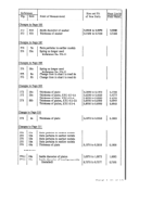
Page 121 is changed as follows.
(5) Drill the remaining two dowel pin holes, Change Paragraph 141a to read:
spacing them 120 degrees apart.
a. Install 1-1/4 inch plugs 35 or 36 if they were
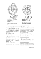
(6) Install the three pins (Fig. 149.1), driving
removed. Torque plugs 35 and 36 to 90-110 pound-
them 0.005 to 0.015-inch below the sleeve surface.
feet. Install 1-inch plugs 33, 39 or 41 if they were
removed. Torque plugs 33, 39 and 41 to 70-90
(7) Line bore sleeve 18 (Fig. 373, fold-out 2) to
pound-feet. Install 1-1/2 inch plugs 40 if they were
6.2990-6.002 inches diameter, with a finish of 100
removed. Torque plugs 40 to 110-130 pound-feet.
RMS (Fig. 149.1).
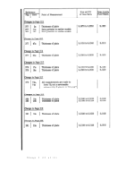
Page 123 is changed
as follows.
Page 110 is changed as follows.
Add following sentence to Paragraph 143u:
Change Paragraph 98c to read:
c. Do not remove inserts 137,140,112,113 and
122 (Fig. 373, fold-out 2), or sleeves 119,120,134,
136 or 139 from input transfer housing assembly
111 unless replacement is necessary. If necessary to
remove a bushing or insert, refer to par. 72 for the
proper procedure. If present, do not remove bush-
ing assembly 118.
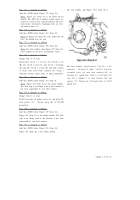
Figure 151 is changed as follows:
Dimension for line bore should be added to read
7.0864-7.0876 inch diameter.
Note that later models have plugs located differently
from that shown in figure 161.
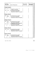
Page 124 is changed as follows.
Paragraph 146a is changed to read:
a. If removed, install l/4-inch plugs 49 and 50.
Torque plugs 49 and 50 to 96-120 pound-inches.
Install preformed packing 59 into end cover 48.
Page 127 is changed as follows.
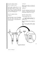
Output coupling and coupling retainer as shown in
Figures 172 and 173 and as addressed in Steps s and t
are present only in earlier models.
Change 2 (3 of 13)
Back to Top

