TM-9-2520-234-35 - Page 14 of 323
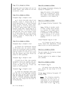
Page 192 is changed as follows.
Step 27 is changed as follows:
Install engine coupling shaft (A). For
later models, install two 1/2-13 x 5-1/4
bolts (B), four 1/2-13 x 6 bolts (C) and
four 7/16-14 x 1-1/2 bolts (D) with lock
washers. Torque 1/2-inch bolts (B) and
7/16-inch
(C) to 67-80 pound-feet. Torque
bolts (D) to 42-50 pound-feet.
Page 193 is changed as follows.
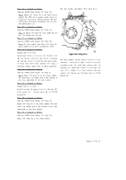
Add Step 3.1:
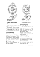
Install lock plate (A) (fig. 359) [without
lock strips (B)] and four 5/8-18 x 2-1/2
bolts (C). Using a 15/16-inch wrench,
torque the bolts to 134-160 pound-feet to
Add Step 3.2:
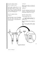
Remove the four 5/8-18 x 2-1/2 bolts (C)
and lock plate (A). Measure the gap shown
in Figure 358.1
Add Step 3.3:
If necessary, add shims 51 (fig. 385.1., fold-
out 14.1) so that the gap after shim in-
stallation is 0.008-0.012 inch. Leaving
selected shims installed, go on to Step 4.
Page 202 is changed as follows.
Change paragraph 235d
to read:
d . Standard Torque Listings.
Fo r
torque values,
refer to the individual
procedure steps.
seat all the parts.
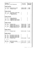
Pages 203 through 229 are changed as
follows.
The far right column marked “Depot
Maint." is no longer used at this repair
level.
(10 of 13) Change 2
Back to Top

