TM-9-2520-234-35 - Page 9 of 323
Page 129 is changed as follows.
Delete Paragraph 151 m . The shroud is no
longer required.
Page 134 is changed as follows.
Paragraph 153at is changed to read:
at . Remove left-brake apply ca m
stationary ring (fig. 190). Remove ring
seal and expander from ring.
Paragraph 153au is changed to read:
au . Remove right-brake applv cam
stationary ring (fig. 191).
seal and expander from ring.
Paragraph 156a is changed to
a . Install any plugs in
rear housing 25 that were
Remove ring
read:
transmission
removed for
cleaning purposes. Torque 3/8-inch plug
22 (fig. 379, fold-out 8) to 12-16 pound-
feet.
Torque l-inch plug 27 to 70-9 0
pound-feet.
Paragraph 156b is changed to read:
b . Install new ring seal and expander
onto right-brake apply cam stationary ring
(fig. 191).
Paragraph 156d is changed to read:
d . Install new ring seal and expander
onto left-brake apply cam stationary ring
(fig. 190).
Page 138 is changed as follows.
Paragraph 156ag is changed to read:
ag.
Install the left-follower link shaft
plug (fig. 198). Torque the 3/8-inch plug
to 12-16 pound-feet.
Paragraph 156aj is changed to read:
aj.
Install the right-follower link
shaft plug (fig. 200). Torque the plug to
12-16 pound-feet.
Page 139 is changed as follows.
Paragraph 156ap is changed as follows:
ap . Install the brake coolant pump
idler gear shaft and secure with one
3/8-16 x 3-1/4 cap screw (fig. 176).
Torque
the
cap
screw
to
26-32
pound-feet.
Add the following Note immediately
below Paragraph 158 heading:
Note. The pinions in this planetary
carrier are a matched set. There-
fore, failure of one pinion requires
replacement of the complete set.
Page 141 is changed as follows.
Change Not e following Paragraph 161
heading to read:
Note . Chill steer planetary car-
rier spindles 11 (fig. 378, fold-out
7) in dry ice for approximately one
hour prior to installation. Handle
chilled parts with gloves.
Add this Not e following Paragraph 161k.
—
Note . Chilling of spindles results
in "frost" initially which ultimate-
ly is moisture.
If a rebuilt carrier
assembly is not being installed in a
transmission in the near future,
apply a coating of oil aroun d
spindle locations to avoid rust
oxidation.
Page 144 is changed as follows.
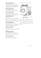
The part number for the compressing tool
in Figure 210 is 8355784.
Delete both Notes from Page 144 follow-
ing Steps k and 1.
—
—
Page 145 is changed as follows.
Delete Not e following Paragraph 173a (l).
Change 2 (5 of 13)
Back to Top

