TM-9-2520-254-34 - Page 24 of 126
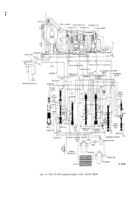
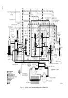
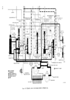
c. Front Governor (Gl) Circuit
(blue, black—
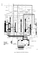
fig. 2-5). The front governor (G1) circuit functions
as described in paragraph 2-15c
d. Rear Governor (G2) Circuit
(green, black—
fig. 2-5). The rear governor (G2) circuit functions
as described in paragraph 2-15d except that in-
creased G2 pressure,
in the absence of in-
termediate-low inhibitor pressure, has forced the
low-intermediate shift plug, shift valve, and blocker
plug upward. This allows main pressure to be
directed to the intermediate-high shift valve bore.
Low-range clutch pressure is exhausted when the
low-intermediate shift valve is upward.
e. Intermediate-Range Clutch Circuit
(red,
yellow—fig. 2-5). At the intermediate-high shift
valve,
main pressure. is connected to the in-
termediate-range clutch pressure line. This applies
the clutch.
j. Throttle Valve (TV) Circuit (blue,
yellow—fig.
2-5). The throttle valve (TV) circuit functions as
describe in paragraph 2-15f.
2-15
Back to Top

