TM-9-2520-254-34 - Page 15 of 126
to the reverse-range planetary carrier and rotates
with it. Since the carrier is splined to the trans-
mission output shaft,
rear governor pressure is
proportional to transmission output speed. The rear
governor functions only during vehicle forward
movement. Rear governor pressure is called G2
pressure.
2-8. Transmission Housing
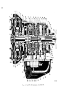
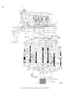
The transmission housing (31, fig. 2-1) is an
alum inure
casting. The one-piece housing is
machined to provide a mounting which mates with
either the engine flywheel housing or a mounting
face on a transfer housing. It is open at the front
and machined internally to receive all of the range
gearing and clutches, and rear oil pump. Openings
are provided at each side, with machined pads for
mounting power takeoff units. The bottom of the
housing is machined for the oil transfer plate and
oil pan.
2-9. Oil Filter and Oil Pan
a. Oil Filter Components
(fig. 2-1). A pressed
steel oil filter can assembly (55)
is bolted beneath
the valve body assembly (48). This assembly
encloses a throw-away filter element assembly. Oil
enters the can assembly through a horizontal
pickup tube located near the bottom of the oil pan.
Oil, after passing from the outside to the inside of
the filter element, leaves the can assembly through
tubes (4.5 and 57) leading to the front and rear oil
pumps. The filter element is accessible from the
left-front side of the oil pan.
b. Transmission Oil Pan
(fig. 2-1). The oil pan
(42) is pressed steel and serves as the transmission
oil sump.
It is attached to the bottom of the
transmission housing by 26 bolts which pass
through a flared rim. The oil pane encloses an oil
filter (55) and can, control valve assembly (48),
and oil transfer plate (50). Fittings are provided for
the oil filler, drain plug, and for retaining the oil
filter element.
2-10. Transmission Shafts
a. Converter Turbine Shaft
(fig. 2-1). The
transmission has two shafts which transmit all
torque. The turbine shaft (59) is the longer shaft. It
is splined at both ends and has drilled passages.
The front passage directs lockup pressure to the
lockup clutch. The rear passage carries lubricating
oil. The converter turbine (6) is splined to the front
of the shaft. The high-range clutch housing (16),
intermediate-range sun gear (53), and the low-
range sun gear (46) are splined to the rear. The
turbine shaft transmits torque from the turbine to
the range-gear section of the transmission.
b. output Shaft
(fig. 2-1). The transmission
output shaft (33) is an integral part of the low-
range planetary carrier and output shaft assembly.
The carrier is the large, front portion of the
assembly. The shaft is splined for approximately
one half its length at the rear. The reverse-range
planetary carrier assembly (37), speedometer drive
g-ear (34), and the output drive flange (35) are
splined to the shaft. A bushing at the front supports
the rear of the turbine shaft (59).
2-11. Oil Transfer Plate, Valve Body, and
Controls
a. Oil Transfer Plate
(fig. 2-1). A cast aluminum
plate (50), bolted to the bottom of the transmission
housing (31), provides a mounting for the control
valve body assembly (48). Holes and passages in
the transfer plate route oil flow and pressure
between the transmission housing and various
valves in the valve body. A secondary function of
the oil transfer plate is the retention of the two
range clutch anchor pins.
b. Control Value Body Assembly
(fig. 2-1). The
control valve body assembly (48) is mounted on the
oil transfer plate (50) within the oil pan (42). The
assembly includes a system of valves and control
devices, all of which operate automatically with the
exception of the manual selector valve and throttle
valve (TV). Pressure regulation, shifts between
ranges, lockup control, and clutch apply regulation
are the functions of this assembly.
c. Manual Controls.
The manual selector valve
and throttle valve in the control valve body
assembly are actuated by two lever and shaft
assemblies. The levers are inside the oil pan area.
The shafts are integral with the levers and extend
through a single opening to the outside of the
transmission housing at the left side. The selector
valve shaft is the larger and is hollow. The small
throttle valve (TV) shaft is solid, and passes
through the hollow center of the selector valve
shaft. Seal rings prevent oil leakage. Snap rings
retain the shafts. Splines at the outer ends of the
shafts provide points for attaching external control
levers.
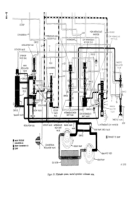
d. operation of Value Body and Controls.
Because of the importance and complexity of the
valve body and controls, and their interrelation
with other components of the transmission, a
separate section in this chapter is devoted to the
hydraulic system.
Refer to paragraphs 2-12
through 2-21.
2-6
Back to Top

