TM-9-2520-254-34 - Page 16 of 126
Section II. OPERATION OF HYDRAULIC SYSTEM
2-12. Hydraulic Schematics
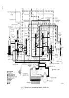
a. Full and Partial Schematics.
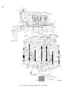
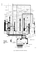
A schematic
diagram of the entire hydraulic system is illustrated
in figure 2-2. Eight partial schematics in color (fig.
2-3 through 2-10) illustrate the operation of the
hydraulic system under various conditions ex-
plained in paragraphs 2-14 through 2-21.
b. Valve Positions.
(1) In
the partial schematics (fig. 2-3 through
2-10). valves and other moving parts are shown in
their proper positions for the conditions illustrated.
Some valves will be at either one extreme or the
other of their movement, while others are at some
intermediate position. Thus, those at intermediate
positions show only the approximate degree of
movement under certain conditions.
(2) It must be remembered that input speed,
output speed. throttle opening, selector position,
and oil temperature and viscosity will affect the
degree of movement and positions of certain valves.
c. Colors Indicate Hydraulic Circuits.
Separate
colors or
color
combinations
indicate
each
hydraulic circuit.
Color blocks on the partial
schematics identify each circuit. Areas not colored
are usually filled with oil which is neither flowing
nor under pressure.
Such areas are inactive,
contribute nothing to hydraulic action, and may be
disregarded.
2-13. Torque Converter or Lockup Drive
The torque converter and lockup clutch must be
considered as part of the hydraulic system since
both require oil for operation. Therefore, in all
explanations of transmission operation, keep in
mind that the input drive may be direct (through
the applied lockup clutch) or hydraulic (through
the torque converter). These terms are reduced to
“lockup” and “converter” operation in the ex-
planations which follows.
2-14. Hydraulic System — Neutral Operation
a.
Main Pressure Circuit
(red—fig. 2-3).
(1)
Engine idling.
Figure
2-3 illustrates
neutral operation of the transmission while the
engine is idling and the engine throttle is closed.
The transmission is in converter operation.
2-7
Back to Top

