TM-9-2520-254-34 - Page 20 of 126
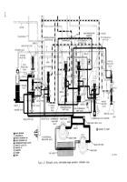
c. Front Governor (Gl) Circuit (blue,
black—
fig. 2-3).
(1) Pressure or flow in the front governor
circuit is caused by the front fluid velocity governor
(para 2-7). The three branches of the circuit
connect with the main regulator plug, lockup valve
plug, and a ball check valve at the right of the
manual selector valve.
(2) In neutral (and reverse) the ball check
valve is always open (downward) because there is
no pressure below the ball to seat it (upward). The
line, below the ball, exhausts around the manual
selector valve stem. Thus, there is a flow, but no
pressure in the front governor circuit. As a result,
the main regulator plug and lockup valve plug
remain down. Main pressure is not modulated by
front governor pressure, and lockup cannot occur in
neutral operation.
2-15. Hydraulic System—Low-Range Oper-
ation
a.
Main Pressure Circuit
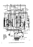
(red—fig. 2-4).
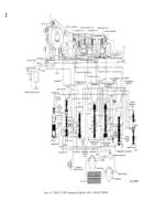
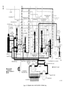
(1) Figure 2-4 illustrates low-range operation
of the transmission while engine throttle is open
and the lockup clutch is engaged. The explanations
of circuits and components, below, will refer to
previous explanations where applicable.
(2) Oil is pumped into the main pressure
circuit by both oil pumps (when vehicle is moving
forward) in low-range operation. The rear pump
check valve is open (upward) when the rear pump
is rotating.
Oil is distributed as described in
paragraph 2-14a (2).
(3) At the throttle valve, during full-throttle
operation as illustrated, the throttle valve (TV) and
throttle (T) circuits are charged. Refer to
f
and
g
below for explanations of these circuits.
(4) At the manual selector valve, main
pressure is directed to four points. These are the
front governor check valve ball, low-intermediate
shift valve. high-intermediate inhibitor circuit, and
intermediate-low inhibitor circuit. Main pressure
seats the check valve ball (upward) in the front
governor
(G1) passage and prevents governor
pressure from exhausting.
(5) At the low-intermediate shift valve, main
pressure divides to two branches. The upper branch
is blocked but the pressure exerted against valve
lands of different diameters exerts a downward
force on low-intermediate shift valve. This pressure
acts only when the valve is downward and prevents
cycling of the valve.
A similar downward force,
resulting from unequal valve land diameters, is
exerted in the lower branch. These forces act only
when the valve is downward. The lower branch
connects. when the low-intermediate shift valve is
downward, with the low-range clutch (e below).
(6) Oil flowing to
the high-intermediate
inhibitor circuit is restricted by an orifice before it
reaches the inhibitor valve and the intermediate-
high blocker plug. Refer to paragraph 2-20a for an
explanation of the high-intermediate
inhibitor
circuit.
(7) Oil flowing
to the intermediate-low
inhibitor circuit is restricted by an orifice before it
reaches the inhibitor valve and low-intermediate
blocker plug. Refer to paragraph 2-21a for an
explanation
of the intermediate-low
inhibitor
circuit.
(8) At the lockup valve, which is in lockup
position (upward), main pressure divides to two
branches. The lower branch is still blocked as in
converter operation. The upper branch is open to
lockup feed. Lockup feed also divides to two
branches. The upper branch directs pressure,
through an orifice, to the area between the main
regulator valve and regulator plug. Here, main
pressure forces the plug downward, and forces the
main regulator valve upward. This decreases main
pressure.
(9) The lower branch of lockup feed enters the
flow valve bore and supplies pressure for lockup
operation (except when flow valve is downward).
Refer to
i
below for explanation of the lockup
circuit.
(10) Main pressure enters the flow valve bore
and acts as described in paragraph 2-14a (6).
(11)
At the main regulator valve, main
pressure raises the valve as described in paragraph
2-14a (7). However, the valve is moved farther
upward in the bore than shown in figure 2-3,
allowing oil to escape to the sump as well as to the
converter-in circuit. Refer to
b
below for ex-
planation of the converter-in circuit during lockup
operation.
(12) At the trimmer valve, main pressure
enters the valve bore at two points. At the upper
point (orifice at right side of bore), oil fills the area
above the trimmer plug. Main pressure is at full
value in this area because no oil can escape past
the extender valve ball held downward by main
pressure.
(13) At the lower end of the trimmer valve,
main pressure enters the trimmer valve bore,
connects with the area within the valve through an
orifice. and exerts equal pressure above and below
the valve. The springs above and below the trimmer
plug hold the trimmer plug and valve in the
positions illustrated. The trimmer is set for action
when in this condition. Refer to paragraph 2-16i
for explanation of trimmer operation.
2-11
Back to Top

