TM-9-2520-254-34 - Page 12 of 126
()()
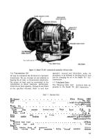
() 1
02
63
04
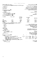
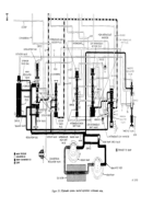
Chmverter pump cover hub
Turbine hub
Gmverter pump cover drive stud
Converter pun] p cover assembly
Lockup clutch plate
Gmverter turbine assembly
Gmverter stator and cam assembly
Converter pump assembly
Pun] p hub ball bearing assembly
Converter ground sleeve
Front oil pump
I)iaphragm assembly
H igh-rarrge clutch housing support flange
Front fluid velncity governor
H igh-ratrge clutch piston
High-range clutch housing assembly
High-range clutch plate
Intermediate-rattge
clutch back plate
1 nte-rrnediate-r ange clutch plate
Intermediate-range ring gear
M
otemnediate-range
clutch piston
Intermediate-range clutch piston housing assembly
Low-range ring gear
Low-range clutch plate
Low-range clutch piston
Lnw- and reverse-range clutch piston housing assembly
Reverse-range clutch piston
Reverse-range clutch plate
Reverse-range ring gear
N everse-range clutch back plate
Tramm ission housing
Near oil pump
Transmission output shaft
Speedometer drive gear
Transm issinn mltput flange
output flange ball bearing
Reverse-range carrier assembly
Reverse-range sun gear
Rear fluid velocity governor
Reverse-range sun gear shaft
Low- and reverse-range clutch anchor pin
(}il pan
Reverse-range
clutch return spring
[ )il transfer tube
Rear oil pump intake tube
Low-range sun gear
Low-range clutch return spring
Control valve assemblv
Oil transfer tube retaining ring
oil transfer plate
Itltermediate-range clutch return spring
lntm-meriiate-ran~e
clutch anchor pin
Intermediate-range sun gear
Itlternlediate-ra]lge
carrier assembly
(N filter
Back plate spacer
Frnnt oil pump intake tube
High-range clutch piston return spring
Converter t~bine shaft
Pump hub
Freewheel roller
Lockup clutch back plate
Freewheel roller race
Lockup clutch piston assembly
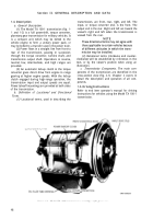
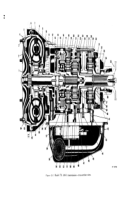
2-2. High-Range Clutch and Power Takeoff
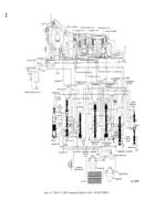
(fig. 2-l).
a. High-Range Clutch Components (fig. 2-1).
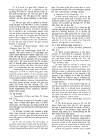
(1) The high-range clutch consists mainly of
housing (16), piston (15), piston return springs
(58), four internal-splined, bronze-faced steel
clutch plates, three external-tanged steel plates
(17), and a steel reaction plate.
(2) The housing (16) has a 6/8-pitch, 57-
tooth power takeoff drive gear, integrally machined
at its outer circumference. The housing has internal
splines in the hub which connects it to the turbine
shaft (59).
(3) The external-tanged clutch plates (17)
engage the housing (16). The internal-splined
plates engage a hub which is integral with the
intermediate-range planetary carrier (54).
b. Operation of High-Range Clutch
(fig. 2-1).
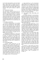
(1) Power from the turbine (6) is transmitted
to the clutch housing (16) through the turbine shaft
(59) and the hub splines. When the clutch is
released, the housing and three external-tanged
clutch plates rotate but do not drive the four in-
ternal-splined plates. When the clutch is applied,
hydraulic pressure pushes the piston (15) rearward
and compresses all seven clutch plates against the
clutch reaction plate. This grips the internal-splined
plates and causes them to rotate with the external-
tanged plates and housing. The internal-splined
plates drive the intermediate-range planetary
carrier.
(2) The housing (16) rotates when the turbine
shaft (59) rotates. The shaft (59) rotates when the
turbine (6) rotates. Thus, the housing (16) can
rotate in neutral, reverse gear, or any forward gear
when engine power is applied through the converter
by speeding up the engine. For this reason the
power takeoff drive gear is part of the housing. Its
teeth mesh with a driven gear in the power take-off
assembly (or assemblies) which may be mounted on
either side of the housing (31).
(3) In high-range operation, torque is trans-
mitted at the same speed from the turbine shaft
(59) to the intermediate-range planetary carrier
assembly (54). The intermediate-range planetary
carrier (54) is attached to the low-range ring gear
(23). The low-range sun gear (46) is splined to the
turbine shaft (39). Thus, two members of the low-
range gear set are rotating at the same speed as the
high-range clutch. The third member (low-range
planetary carrier)
is meshed with these two and,
therefore. must also rotate at the same speed. This
results in the transmission output shaft (33) being
driven at the same speed as the turbine shaft (59).
2-3
Back to Top

