TM-9-2520-254-34 - Page 18 of 126
(2) Neutral.
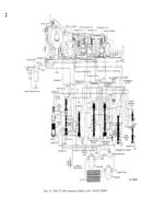
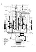
In neutral, only the front oil
pump is rotating. Oil is picked up from the sump
through the oil filter element and pumped into
main pressure circuit. Through various branches of
the main pressure circuit, oil is directed to the
throttle regulator valve, manual selector valve, low-
intermediate shift valve, lockup valve, flow valve,
main regulator valve, and trimmer valve.
(3)
Throttle regulator valve.
At the throttle
regulator valve, main pressure is blocked because
the valve is downward (when engine throttle is
closed, throttle valve is against the stop). Opening
the throttle will move the throttle valve upward
against a spring. The spring will push the throttle
regulator valve upward and allow oil to flow into
the throttle valve (TV) circuit. Further movement
will allow oil to flow into the throttle (T) circuit. T
and TV are regulated pressures which increase as
the throttle is opened. Their effects will be ex-
plained in subsequent paragraphs.
(4)
Manual selector valve.
At the manual
selector valve, main pressure fills the valve bore at
the valve detent area. In neutral position of the
manual selector valve, main pressure flows only to
the area above the low-intermediate shift plug. This
holds the low-intermediate shift plug downward
and the low-intermediate shift valve and blocker
plug upward. This action is of no consequence
during neutral operation.
(5)
Lockup valve.
At the lockup valve, main
pressure is available for lockup but is blocked
because the valve is downward. The valve will
remain downward in neutral because no front
governor (G1) pressure is available in neutral or
reverse (c below).
(6)
Flow valve.
At the flow valve, main
pressure enters the valve bore at three points. In
neutral, pressure at these three points is equal.
Pressure at the middle point is blocked. The lower
surface area of the valve is slightly greater than the
upper surface area. As a result, the valve is held
upward against its stop. The action of the flow
valve is dependent upon a significant flow of oil
through the orifice at the left of the valve (para 2-
16a(1)). A branch of main pressure extends from
the flow valve bore, when the flow valve is upward,
to the area between the extender valve and the
extender valve ball above the trimmer.
(7)
Main regulator valve.
At the main
regulator valve, pressure acting against the lower
surface area of the valve’s large land raises the
valve against spring pressure. This produces main
pressure and provides oil for charging the torque
converter (b below).
(8)
Trimmer valve.
At the trimmer valve, main
pressure enters the valve bore at two points. Oil
passing into the bore at the lower end of the
trimmer valve flows also through the valve’s orifice.
This pressure is exerted against the bottom of the
trimmer plug but, due to main pressure plus spring
pressure above the plug, cannot lift it. Oil entering
the right side of the trimmer valve bore through an
orifice cannot escape past the extender valve ball
because main pressure plus spring pressure holds
the ball seated. The trimmer is inactive during
neutral operation but is set for operation and will
act when any shift (except lockup) manual or
automatic occurs. Refer to paragraph 2-16i, for
trimmer operation.
(9)
Rear pump check valve.
The rear pump
check valve ball is seated during neutral operation
(when vehicle is standing) because the rear pump is
not operating. Oil from the main pressure circuit
passes through an orifice between the front and rear
pump output lines and supplies oil, through a
second orifice, to fill the rear governor pitot ring.
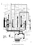
b. Converter-In Circuit
(yellow—fig. 2-3).
(1) The converter-in circuit is supplied from oil
escaping at the main regulator valve. The volume of
this oil varies with engine speed (and vehicle speed
when vehicle is moving forward). Slight and / or
temporary changes in volume will be caused by
shifting, action of the throttle valve, lockup valve,
trimmer valve, or inhibitor valves. However, in
neutral, only the throttle valve can be actuated.
(2) Converter-in oil flows to three points.
Trhese are an orifice to the converter-in line, the
lockup valve, and the converter-in regulator valve:
In neutral, or at any other time the lockup valve is
downward (converter operation), the orifice is
ineffective. It is ineffective because oil can flow
unrestricted to the converter-in line through the
lockup valve bore. The branch leading downward
to the converter-in regulator valve exhausts ex-
cessive oil to the sump when the valve opens.
(3) The converter-in regulator valve opens
when the pressure in
the circuit exceeds a
predetermined value. Input speed (and output
speed) and position of the lockup valve influences
its opening and degree of opening. It is shown in the
closed position in neutral because the engine is
idling, only the front pump is supplying oil, and
there is unrestricted flow to the converter.
2-9
Back to Top

