TM-9-2520-254-34 - Page 70 of 126
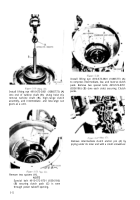
Figure 5-54.
Figure 5-56.
5-9. Cleaning
Refer to paragraph 5-2 for cleaning recom-
mendations.
5-10. Inspection and Repair
Refer to paragraph 5-3 for general inspection and
repair
recommendations. Repair and overhaul
(rebuild) points of measurement for fits, clearances,
and wear limits are indicated by small letters in
figure 5-53. Refer to paragraph 6-3 and table 6-3
for wear limits information.
5-11. Assembly
All items not covered in
a
through
c
below are
installed as outlined in paragraph 5-58, steps 31
through 38 (fig. 5-114 through 5-121). No
overhaul (rebuild) of such components is required
or recommended.
a. Lockup Clutch Assembly
(fig. 5-53).
(1)
If bushing (5) in converter pump cover hub
was removed, use replacer 5120-572-8656 and
handle 5120-316-9182 (fig. 5-57) to install new
bushing.
(2) Install seal retainer (6) on converter pump
cover (4) hub with larger diameter toward open end
of cover. Install oil seal ring (7).
(3) Install piston seal ring (10) in groove of
lockup clutch piston (8) outside diameter.
(4) Insert lockup clutch piston (fig. 5-58) into
converter pump cover with stamped balance marks
(if any) alined so that piston guide pins will enter
nearest holes in piston.
Figure 5-55.-Flattening lock strip tab.
5-20
Back to Top


