TM-9-2520-254-34 - Page 71 of 126
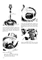
Figure 5-57.
Figure 5-58.
NOTE
(4) Place converter pump bearing retainer
To make installation of lockup clutch
piston assembly easier, put a pencil mark in
line with pin nearest orifice in piston (when
balance marks are alined as in figure 5-58).
Then, when piston assembly is being in-
stalled, use pencil mark as a guide to
location of pin beneath orifice. One
recessed hole in piston is concentric with
orifice. Rotate piston slightly, if necessary,
during installation to insure that piston
engages pins. To make certain that piston
is properly seated, measure distance from
pump cover mounting surface to piston;
this distance should be approximately 1
1
/
2
inches.
CAUTION
Lockup clutch will not release if piston is
not engaged with pins.
(5) Install snap ring (9) on converter pump
cover (4) hub.
b. Converter Stator and Cam Assembly
(fig. 5-
53).
(1) Position converter stator and cam
assembly (fig. 5-59) with largest inside diameter
up. Install 10 springs in cam pockets. Ends of
springs must be toward center of stator and cam
assembly and in deep end of cam pockets. Relative
position of spring and roller is shown.
(2) Install holder assembly 4910-572-8588
(fig. 5-60)
in converter stator and cam assembly.
Install 10 rollers in cam pockets. Lubricate rollers
and springs with transmission oil.
(3) Install freewheel roller race (35), coun-
terbored side facing away from stator and cam
assembly (16).
into stator and cam assembly.
Rotate freewheel roller race in a clockwise direction
while installing, and seat on holder assembly.
(4) Hold freewheel roller race in place, and
turn stator and cam assembly over (fig. 5-61).
Remove holder assembly 4910-572-8688 by
pulling on chain provided.
(5) Seat freewheel roller race (35 ) on needle
bearing assembly (17). Position stator and cam
assembly so freewheel roller race is upward until
read y for installation.
c. Converter Pump Assembly
(fig. 5-53).
(1) Position new converter pump hub gasket
(26) on mounting face of converter pump (29).
(2) Install ball bearing (23) in converter pump
hub (24).
(3) Install pump hub in converter pump bore,
and aline holes.
(22) over ball bearing, and aline holes (fig. 5-56).
(5) Install eight bolts (20) through four new
tab locks (21). Tighten bolts to 9 to 11 pound-feet
torque.
(6) Bend pointed corners of lock tabs up
against flat sides of bolt heads to lock bolts.
(7) Replace converter pump flange bolts (30),
as necessary, and make sure weights (31) (if any)
are in place if pump bolts have been removed.
(8) Install hook-type seal ring (25) on pump
hub (24).
5-21
Back to Top


