TM-9-2520-272-40 - Page 277 of 620
TM 9-2520-272-40
0035
SUSTAINMENT MAINTENANCE
REPLACE LEFT OUTPUT SHAFT
INITIAL SETUP:
Tools and Special Tools
Hammer, Hand, Soft-Face, Dead Blow, 52 oz
(WP 0079, Item 19)
Heater, Gun-Type, Electric (WP 0079, Item 20)
Press, Arbor, Hand, 25 Ton (WP 0079, Item 28)
Tool Kit, General Mechanic’s (GMTK) (WP 0079,
Item 45)
Materials/Parts
Block, Wood, Lumber, Soft Wood (WP 0078, Item 3)
(2 - 16 in. lengths)
Carbon Dioxide, Technical (Dry Ice) (WP 0078, Item
4)
Gloves, Leather (WP 0078, Item 8)
Lubricating Oil, Engine (WP 0078, Item 10)
Petrolatum, Technical (Petroleum Jelly) (WP 0078,
Item 12)
Retainer, Packing (WP 0080, Item 39)
Retainer, Packing (WP 0080, Item 53) (2)
Personnel Required
Track Vehicle Repairer, 91H10 (2)
References
TM 9-2350-277-13&P
Equipment Condition
Transmission removed from vehicle or container (TM
9-2350-277-13&P)
Oil f ll tube assembly removed (WP 0006)
Left cover assembly removed (WP 0033)
REMOVE LEFT OUTPUT SHAFT
NOTE
Make sure that the left cover assembly is turned so that the internal side points up when it is
not on its edge.
Use two wooden blocks to make the left cover assembly level when you put it on its edge. Put
the blocks below the corner nearest to the left output shaft.
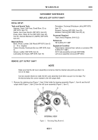
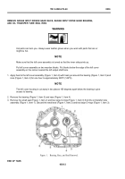
1. Remove the retaining ring (Figure 1, Item 3) that holds the bearing assembly (Figure 1, Item 4) and the left
output shaft (Figure 1, Item 2) from the left cover assembly (Figure 1, Item 1).
Back to Top

