TM-9-2520-272-40 - Page 278 of 620
TM 9-2520-272-40
0035
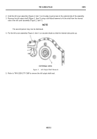
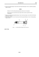
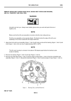
2. Hold the left cover assembly (Figure 2, Item 1) on its edge to get access to the external side of the assembly.
3. Remove the left output shaft (Figure 2, Item 2) using a soft-faced hammer to hit the shaft from the internal
side of the left cover assembly (Figure 2, Item 1).
NOTE
The second person may now be dismissed.
4. Put the left cover assembly (Figure 2, Item 1) on wooden blocks so that the internal side points up.
Back to Top


