TM-9-2520-272-40 - Page 282 of 620
TM 9-2520-272-40
0035
NOTE
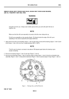
Put the left cover assembly on two wooden block to make it level. Make sure that the left cover
assembly is turned so that the interior side points up.
8. Apply petrolatum to inner surface of seal (Figure 5, Item 9).
9. Turn the left output shaft (Figure 5, Item 2) carefully and push the end of the left output shaft (Figure 5, Item 2)
through the left output seal (Figure 5, Item 9).
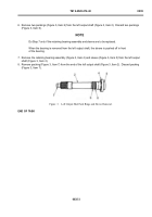
10.Make sure the left output shaft (Figure 6, Item 2) is very straight and tap on the splined end of the shaft (Figure
6, Item 2) to install the bearing assembly (Figure 6, Item 4) in the shoulder on the left cover assembly (Figure
5, Item 1). If the bearing does not install easily, apply heat to the left cover assembly (Figure 5, Item 1) with
heat gun around bearing journal to install bearing.
11. Make sure that the left output seal (Figure 5, Item 9) stays in position in the left cover assembly (Figure 5, Item
1) and that the lip on the seal is not twisted when the left output shaft (Figure 5, Item 2) goes through the left
output seal (Figure 5, Item 9).
NOTE
When the left output shaft and bearing are installed, you will have access to the snap ring
groove in the sleeve at the outer edge of the bearing.
12.Install the retaining ring (Figure 6, Item 3) in the groove in the sleeve (Figure 6, Item 5) above the bearing
assembly (Figure 6, Item 4).
13.Apply lubricating oil to bearing assembly (Figure 6, Item 4).
Back to Top


