TM-9-2520-272-40 - Page 296 of 620
TM 9-2520-272-40
0037
NOTE
Range input drive gear and hydrostatic drive gear will not connect properly with range input
driven gear (Figure 6, Item 6) and hydrostatic idler gear if the incorrect bevel gear driven
shaft was installed.
8. Do a check to make sure teeth on range input drive gear (Figure 6, Item 2) and teeth on range input driven gear
(Figure 6, Item 6) fully engage, and that outer surfaces of gears are on the same plane. If gears are not even,
continue to move gears (Figure 6, Item 2) and (Figure 6, Item 3) until bevel gear driven shaft (Figure 6, Item 9)
and gears (Figure 6, Item 2), (Figure 6, Item 3), (Figure 6, Item 6), and (Figure 6, Item 10) are all synchronized.
CAUTION
Damage to left cover assembly can occur if incorrect bevel gear driven shaft is installed. Make
sure part identif cation as recorded when bevel gear shaft was removed, as well as the length
of shaft before installation.
9. If range input drive gear (Figure 6, Item 2) and hydrostatic drive gear (Figure 6, Item 3) will not install properly,
remove gears (Figure 6, Item 2) and (Figure 6, Item 3) and (Figure 6, Item 6), and bevel gear driven shaft
(Figure 6, Item 9). If the gears install properly go to Repair Left Cover Assembly, WP 0034.
PN
Length
29533537
10.65 in. (27.05 cm), used with rear carrier assembly, PN 29533535
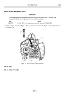
10.Make sure part identif cation of bevel gear driven shaft (Figure 6, Item 9) is correct. Install the correct bevel
gear driven shaft (Figure 6, Item 9) and repeat Step 4 through Step 8.
Back to Top

