TM-9-2540-207-14-P - Page 121 of 288
TM 9-2540-207-14&P
5-77
5.9.4.2 Diagnostic Display Repair (Design Iteration 3 Only)
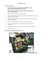
Figure 5-11.
Diagnostic Display
5.9.4.2.1 Removal
1.
Remove Top Cover (ref 5.4.1).
2.
Using a #2 cross-tip screwdriver, remove four (4) screws and star washers taking care to
leave the four (4) metal standoffs in place.
Lift the Diagnostic Display Board separating
the two halves of connector J1 on the underside of the board.
3.
Disconnect the Wiring Harness Connector (J8) from the Diagnostic Display by pressing
connector clip on underside of connector and gently separating the two halves.
5.9.4.2.2 Installation
1.
Place the Diagnostic Display Board onto the threaded posts ensuring that the four (4)
nylon standoffs are in place engaging the two halves of connector J1 on the underside of
the board.
Note: The holes in the Diagnostic Display Board are offset so that the
Board can only be placed in one direction on the posts.
Diagnostic
Display
Board
Back to Top


