TM-9-2540-207-14-P - Page 117 of 288
TM 9-2540-207-14&P
5-73
5.9.3
Fuel Pressure Sensor
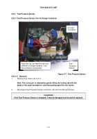
5.9.3.1 Fuel Pressure Sensor (For All Design Iterations)
Figure 5-7.
Fuel Pressure Sensor
5.9.3.1.1 Removal
1.
Remove Top Cover (ref. 5.4.1).
Note: The connector is released by gently lifting the locking tab with the
blade of the small screwdriver, and then pulling apart the two halves.
2.
Disconnect Fuel Pressure Sensor connector (J4) from the Wiring Harness.
! CAUTION !
If the Fuel Pressure Sensor is dropped, it may be damaged and should be replaced.
J4 Logic
Connector
Fuel
Pressure
Sensor
Note that the fuel manifold will look
different in Design Iteration 1 but
the procedure is the same.
Back to Top

