TM-9-2540-207-14-P - Page 108 of 288
TM 9-2540-207-14&P
5-64
6.
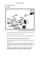
Place the Top Housing onto the Heat Exchanger taking care not to trap or damage the
Wiring Harness. Line up Secondary Air Duct on underside of Top Housing over the air
pipe of the Heat Exchanger.
7.
Using pliers, move one of the 1" metal spring clamps from the Top Housing end along
the Secondary Air Duct Hose and secure to the Heat Exchanger End.
8.
Using a #2 cross-tip screwdriver, secure the Top Housing to the Heat Exchanger using
four (4) screws using pliers, re-set the Secondary Air Duct with the 1" metal spring clamp
so as to remove any kinks or bends in the hose.
9.
Using a 7/16" open ended wrench, install the Exhaust Sensor.
Snap the wide end of the
Exhaust Sensor into the locking clip located on the Heat Exchanger.
10.
Connect the Vent Sensor connector (J5) to the Wiring Harness. Ensure the locking tab is
engaged.
11.
Insert Flame Tube (ref. 5.7.2).
12.
Install Combustor Assembly (ref. 5.7.1).
13.
Install Vent Fan Assembly (ref. 5.6.1).
14.
Install Bottom Shell (ref. 5.4.3).
15.
Install Top Shell (ref. 5.4.2).
16.
Install Top Cover (ref. 5.4.1).
Back to Top


