TM-9-2540-207-14-P - Page 27 of 288
TM 9-2540-207-14&P
2-1
2 INSTALLATION
The heater meets the performance requirements specified when it is mounted, in any position
from horizontal to vertical with the ventilation air inlet level with, or higher than the ventilation air
outlet.
For installation instructions, consult the Vehicle Technical Manual (see Appendix A) for
the appropriate location and mounting methods for the particular vehicle.
2.1
Dual Air Conversion
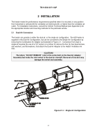
The heater can operate in either the dual air, or the single air configuration.
The A20 heater is
supplied in the Dual Air Configuration, but can be converted to the Single Air Configuration by
removing the Combustion Air Adapter as illustrated in Figure 2-1.
Conversion from dual to
single air requires the use of a 1/4" socket or nut driver to remove the four (4) hex head screws,
star washers, and flat washers, that attach the Dual Air Adapter to the Heater Ventilation Air
inlet.
!CAUTION!
The letters “DO NOT REMOVE” refer to the center bolt on the Dual Air Adapter
Assembly that holds the inlet swivel to the dual air standoff. Removal of this bolt may
damage the swivel seal assembly.
Figure 2.1-1.
Single Air Configuration
Back to Top

