TM-9-2540-207-14-P - Page 35 of 288
TM 9-2540-207-14&P
3-3
3.5 Shutdown Procedures
!WARNING!
In the event that an emergency shut down is required, disconnect
the heater power by
detaching the MS Power Connector from the heater, or disconnect the breaker to the
heater.
!WARNING!
In the event of an emergency shut down, DO NOT TOUCH the heater until it has had
sufficient time to cool.
The Heat Exchanger remains at full temperature and the heater
will not have completed a purge cycle, both of which will pose a safety hazard.
Note: The heater will also automatically shut down if an unsafe operating
condition or component fault is detected.
3.5.1 Manual Shutdown
At any time during Start Up or Run Operation, the heater may be
manually shut down by
moving the START/OFF/RUN switch to the OFF position.
When the switch remains in the OFF
position for more than two (2) seconds, the heater will enter Purge Mode, and after three (3)
minutes will automatically shut off.
During a Manual Shut Down, the Heater’s Diagnostic
Display will report the Heater’s Data Codes (ref. 3.6).
During Shut Down and Purge, the heater will not respond to the Control Box Switch until the
three (3) minute Purge Cycle has been completed.
3.6
Purging the Heater
To manually Purge the heater, hold the Control Box Switch in the “Start” position for ten (10)
seconds, and the let switch go to “Off” position.
The heater will then commence a three
(3)
minute Purge cycle while the Diagnostic Display Code shows
00
for one minute, then cycles
through the Heater Data Codes (ref. 3.6).
3.7
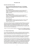
Heater Data Codes Mode
To force the heater to Data Codes Mode, hold the Control Box Switch in the “Start” position for
one (1) second, then let switch return to “Off” position.
The heater will then cycle through the
Data Codes.
Note: If the Diagnostic Display appears blank and the heater is operating,
the Diagnostic Display circuit has failed. Ref to section 5.5.2 for details.
Note: The codes below will appear with a lower case “d” for A20 design
iteration version 3 and above (see Section 5 for more detail on design
iteration versions).
D1
Operation Hours
D2
Number of Starts
D3
Version Level
Table 3.7-1. Data Codes
Back to Top

