TM-9-2540-207-14-P - Page 37 of 288
TM 9-2540-207-14&P
3-5 /3-6 blank
Warning & Shutdown Faults (Continued)
followed by a two (2) second delay.
In the case of a Fuel Pressure Sensor Fault, the Control
Box Lamp will flash in a cycle comprising three (3) quick flashes followed by a two (2) second
delay.
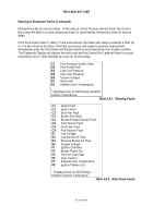
If the Shut Down faults in Table 3-7 are encountered, the heater will cease to attempt a Start Up
or, if in Run mode at the time of the fault occurrence, will cease to produce heat and will
immediately enter the Shut Down and Purge modes to avoid operating in an unsafe condition.
The Diagnostic Display will display the fault code and the Control Box Lamp will flash in a cycle
comprising one (1) flash followed by a two (2) second delay.
C7
Fuel Pressure Sensor Fault
C9
Fuel Pump Fault
E2
Low Fuel Pressure
E5
Inlet Over Pressure
E6
System Voltage*
F3
Heat Limit
F6
Ambient Over Temperature
* Displayed only for A20 Design Iteration
Version 3 and above.
Table 3.8-1.
Warning Faults
C1
Ignitor Fault
C2
Ignitor Short
C3
Vent Fan Fault
C4
Burner Fan Fault
C5
Burner/Exhaust Sensor Fault
C6
Vent Sensor Fault
C8
Controller Fault
CA
Fuel Injector Fault
E1
Low Voltage
E3
Low Burner Air Flow
E4
Reverse Burner Air Flow
E6
System Voltage*
F1
Ignition Overtime
F2
Burner Flame Out
F4
Vent Air Over Heat
F5
Over Current
F7
Exhaust Over Temperature
F8
Ignition Flames Out
* Displayed only for A20 Design
Iteration Version 3 and above.
Table 3.8-2.
Shut Down Faults
Back to Top

