TM-9-2540-207-14-P - Page 34 of 288
TM 9-2540-207-14&P
3-2
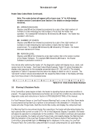
Starting Systems Procedures (Continued).
Note: For A20 Design Iteration Version 3 and up (see Section 5 for details),
the diagnostic display segment steps “BB” and “DD” will appear in lower
case as “bb” and “dd”.
00-11-22-33-44-55-66-77-88-99-AA-BB-CC-DD-EE-FF
Table 3.3-1.
Diagnostic Display, Segment Steps
4.
The heater then enters Stage
03
.
The Vent Fan speed will adjust in preparation for the
ignition process and the heater will begin to deliver fuel to the Burner.
A number of
parameters will be monitored and components checked for failure.
5.
When the heater has achieved ignition, the Ignitor automatically turns off, the Control
Box Lamp illuminates, and the Diagnostic Display will read
04
.
6.
If all systems are operational, immediately after ignition the heater will automatically
ramp the Burner and Vent Fans to full speed, the display will read
05
.
7.
While the heater is setting itself for full Run mode, the display will read
06
.
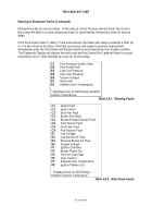
00
Shutdown Purge Mode
01
Self Check
02
Ignitor On
03
Deliver Fuel
04
Ignitor Off
05
Full Heat Ramp
06
Enter Run Mode
07
Low Heat Mode
14
High Heat Mode
99
Vent Only
Table 3.3-2. Operating Modes
3.4 Normal Operation
When the heater is in Run mode, the Diagnostic Display indicates either
07
(Low Heat mode) or
14
(High Heat mode), depending on which heat mode has been selected.
At any time during
Start Up or Run mode the heater can be switched into Low (30,000 BTU/Hr), or High Heat
(60,000 BTU/Hr).
Note: The M1 Tank ONLY is equipped with the ability to run the heater in
“Vent Only” Mode.
In this case the Diagnostic Display reads “99", and the
Control Box Lamp will flash with a cycle comprising two quick flashes
followed by a two (2) second delay.
Back to Top

