TM-9-2815-200-35
ENGINE, WITH CONTAINER:TURBOSUPERCHARGED, DIESEL ,FUEL INJECTION ,90-DEGREE “V” TYPE, AIR - COOLED ,12 - CYLINDER , ASSEMBLY ;MODELS AVDS-1790-2M (2815-856-4996), AVDS-1790-2A AND AVDS-1790-2AM (2815-856-9005)
TECHNICAL MANUAL; DIRECT SUPPORT, GENERAL SUPPORT AND DEPOT MAINTENANCE MANUAL INCLUDING REPAIR PARTS AND SPECIAL TOOLS LISTS
TM-9-2815-200-35 - Page 164 of 779
b.
Removal.
Refer to Table 4-7 for figure
references and instructions pertinent to the
removal of the fuel injector nozzle and holder
assembly.
c.
Testing.
Note.
Before installing injector nozzle on
nozzle tester, thoroughly clean external area to
remove carbon and dirt. Do not allow dirt to
enter nozzle fuel inlet opening. For nozzles that
do not perform properly on nozzle tester refer to
paragraph 4-18 for disassembly sequence and
necessary procedures ‘required to assure a
properly functioning nozzle and holder
assembly.
(1)
Nozzle installation.
Mount the fuel
injector nozzle and holder assembly on the fuel
injector nozzle tester using nozzle attaching tube
-4910-795-7953. The tube should be connected
to the lower connection on the injector nozzle
tester. Close the pressure gage valve and actuate
the pump handle rapidly (approximately 2S
strokes per minute) to expel air from nozzle and
holder and to settle spring and nozzle holding
column.
(2)
Nozzle opening pressure.
Fill reservoir
with sufficient fuel to perform
test. Open
pressure gage valve and actuate tester slowly to
raise pressure. When nozzle opens, gage pressure
must be between 3050 psi (minimum), 3150 psi
(maximum). If this gage reading is not achieved,
nozzle
and holder assembly must be
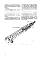
disassembled and spring adjusting spacers (fig.
4-167) added or removed to obtain the proper
pressure reading.
Figure 4-167. Fuel injector nozzle and holder assembly—sectional view.
.
4-8 2
Back to Top


