TM-9-2815-200-35
ENGINE, WITH CONTAINER:TURBOSUPERCHARGED, DIESEL ,FUEL INJECTION ,90-DEGREE “V” TYPE, AIR - COOLED ,12 - CYLINDER , ASSEMBLY ;MODELS AVDS-1790-2M (2815-856-4996), AVDS-1790-2A AND AVDS-1790-2AM (2815-856-9005)
TECHNICAL MANUAL; DIRECT SUPPORT, GENERAL SUPPORT AND DEPOT MAINTENANCE MANUAL INCLUDING REPAIR PARTS AND SPECIAL TOOLS LISTS
TM-9-2815-200-35 - Page 177 of 779
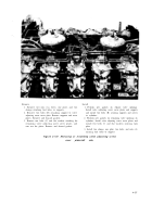
1. Install gage assembly -4910-870-6283 (A) on adapter
- 4910-795-7961 and tighten securely.
2. Crank engine using starter motor and check cylinder
compression. It must be within 330 to 480 psi at engine
cranking speed.
3. Depress gage vent valve (B) to release pressure and
reset gage to zero after compression reading is taken.
Recheck reading. Test compression on all cylinders in
the same manner.
d. Compression
Variation.
After all 12
cylinders are checked,
determine the pressure
difference between high and low cylinder
readings. This variation should not exceed 70
psi.
e. Engine Motoring RPM.
If compression
data exceeds the above
specifications.
the
engine motoring rpm should be checked to be
sure that it is 140 to 180 rpm. Compression
should be checked again to confirm the previous
readings before submitting an engine for
overhaul.
4-23. Adjusting Intake and Exhaust
Valve Clearance
When checking and / or adjusting
clearance,
it is necessary to first remov
valve
e th e
cooling fan vanes, fans, fan shroud, top covers,
and oil coolers to gain access to valve adjusting
screw cover plates.
Refer to Table 4-9 for in-
structions pertinent to the removal of the above
items, and the procedures involved in the ad-
justment
of the intake
and
exhaust valve
clearances.
Figure 4-185. Checking cylinder compres-
sion using gage assembly-4910-870-6283
and compression adapter-4910-795-7961.
4-95
Back to Top


