TM-9-2815-200-35
ENGINE, WITH CONTAINER:TURBOSUPERCHARGED, DIESEL ,FUEL INJECTION ,90-DEGREE “V” TYPE, AIR - COOLED ,12 - CYLINDER , ASSEMBLY ;MODELS AVDS-1790-2M (2815-856-4996), AVDS-1790-2A AND AVDS-1790-2AM (2815-856-9005)
TECHNICAL MANUAL; DIRECT SUPPORT, GENERAL SUPPORT AND DEPOT MAINTENANCE MANUAL INCLUDING REPAIR PARTS AND SPECIAL TOOLS LISTS
TM-9-2815-200-35 - Page 28 of 779
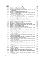
Figure
Number
6-215
6-216
6-217
6-218
6-219
6-220
6-221
6-222
6-223
6-224
6-225
6-226
6-227
6-228
6-229
6-230
6-231
6-232
6-233
6-234
6-235
6-236
6-237
6-238
6-239
6-240
6-241
6-242
6-243
6-244
6-245
6-246
6-247
6-248
6-249
6-250
6-251
6-252
6-253
6-254
6-255
6-256
xxii
Title
Removing or installing camshaft end plate ball bearing retaining ring and
ball bearing.
Removing camshaft end plate ball bearing.
Removing or installing cross shaft levers and bracket.
Removing or installing cross shaft shock spring and control lever.
Disassembling or assembling intermediate throttle lever support.
Disassembling or assembling cross shaft lever, bracket, and adjustable
control rod.
Removing or installing transmission oil cooler bypass valve and shroud plate.
Removing or installing engine right oil cooler hose connector elbows.
Removing or installing engine right oil cooler thermostatic bypass valve.
Oil cooler cleaning equipment setup - schematic diagram.
Disassembling or assembling cooling fan and cooling fan hub.
Removing or installing front and rear cooling fan housings.
Removing or installing cooling fan shroud rails and cover plates.
Removing or installing manifold heater assembly.
Disassembling or assembling manifold heater assembly.
Removing or installing air outlet tube and associated parts.
Removing or installing heater tube.
Removing or installing intake manifold tube attaching parts.
Removing or installing flanges and associated parts from cylinder Nos. 5R
and 6R intake manifold tubes.
Removing or installing intake manifold tubes for cylinder Nos. 3R and 4R.
Removing or installing right intake manifold elbow.
Right and left intake manifold - stud identification.
Disassembling or assembling oil filler and oil level indicator tubes (one piece
oil filler and indicator tubes without splash pan drain ).
Disassembling or assembling oil filler and oil level indicator tubes (improved
oil filler indicator tubes with splash pan drain ).
Disassembling or assembling oil level indicator tube cap (relocated oil filler
tube ),
Disassembling generator cradle, support, and “U” bolt.
Removing or installing fuel check valve tubes and fittings.
Deleted
Fuel check valve flow diaphragm.
Disassembling or assembling primary fuel filter.
Disassembling or assembling secondary fuel filter.
Disassembling or assembling fuel/ water separator.
Disassembling or assembling secondary fuel filter and
drain valves.
fuel / water separator
Comparison of serviceable original production and improvised design sleeves
- fuel injection pump tube ends.
Comparison of serviceable sleeves - injector nozzle tube ends.
Disassembling or assembling generator air intake tube assembly.
Disassembling or assembling manifold heater fuel filter.
Disassembling or assembling fuel injection pump drive splined coupler.
Disassembling or assembling fuel injection pump drive diaphragm coupler.
Piston oiler nozzle and holder assembly.
Time totalizing meter.
Time totalizing meter electric reset device - 6645-179-2712.
Page
6-181
6-181
6-181
6-182
6-182
6-183
6-185
6-186
6-186
6-187
6-190
6-191
6-192
6-194
6-195
6-195
6-196
6-196
6-196
6-197
6-197
6-198
6-199
6-200
6-200
6-201
6-203
6-204
6-204
6-205
6-206
6-207
6-208
6-210
6-211
6-212
6-214
6-215
6-216
6-216
6-217
6-218
Back to Top

