TM-9-2815-200-35
ENGINE, WITH CONTAINER:TURBOSUPERCHARGED, DIESEL ,FUEL INJECTION ,90-DEGREE “V” TYPE, AIR - COOLED ,12 - CYLINDER , ASSEMBLY ;MODELS AVDS-1790-2M (2815-856-4996), AVDS-1790-2A AND AVDS-1790-2AM (2815-856-9005)
TECHNICAL MANUAL; DIRECT SUPPORT, GENERAL SUPPORT AND DEPOT MAINTENANCE MANUAL INCLUDING REPAIR PARTS AND SPECIAL TOOLS LISTS
TM-9-2815-200-35 - Page 291 of 779
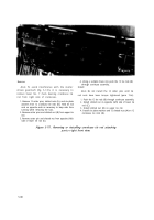
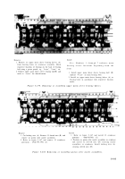
Remove
Install
1. Remove six upper main sleeve bearing halves (A)
Note.
Numbers 1 through 7 indicate mai n
from bearing bores in crankcase assembly. Mark
bearing sleeve locations beginning from th e
respective locations of bearings on the back of bearing
half using a grease pencil; e.g., “l-case”, “2-case”, etc.
front .
2. Remove upper main thrust sleeve bearing half(B) and
mark as “4-case” for identification.
1. Install upper main thrust sleeve bearing half (B)
marked “4-case”
in main bearing bore.
2. Install six upper main sleeve bearing halves (A) in
bearing bores in accordance with respective location
marks.
Figure 5-179. Removing or installing upper main sleeve bearing halves .
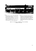
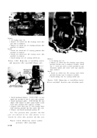
Remove
Install
1. Cut locking wire (A). Remove 12 slotted nuts (B) and
1. Refer to figure 5-147 and install 12 crankcase
remove six piston oiler nozzle assemblies.
protectors
-
(C).
2. Refer to figure 5-147 and remove 12 crankcase
2. Position six piston oiler nozzle assemblies in crankcase
protectors - 4910-795-7951 (C).
and install 12 slotted nuts (B) securing nozzle
assemblies to crankcase. Install locking wire (A)
securing slotted nuts (B).
Figure 5-180. Removing or installing piston oiler nozzle assemblies .
5-105
Back to Top


