TM-9-2815-200-35
ENGINE, WITH CONTAINER:TURBOSUPERCHARGED, DIESEL ,FUEL INJECTION ,90-DEGREE “V” TYPE, AIR - COOLED ,12 - CYLINDER , ASSEMBLY ;MODELS AVDS-1790-2M (2815-856-4996), AVDS-1790-2A AND AVDS-1790-2AM (2815-856-9005)
TECHNICAL MANUAL; DIRECT SUPPORT, GENERAL SUPPORT AND DEPOT MAINTENANCE MANUAL INCLUDING REPAIR PARTS AND SPECIAL TOOLS LISTS
TM-9-2815-200-35 - Page 286 of 779
Remove
Note.
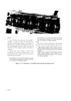
The main bearing caps are marked 1
through 7
(front to rear) to identify their
locations. Identifying numbers also appear on
bearing web in crankcase assembly. The caps are
not interchangeable with each other and must be
returned to their original positions during in-
stallation.
Note.
Do not use a scriber or other sharp
instrument for marking bearing halves. It is
recommended that a grease pencil be used for
mat-king bearing halves.
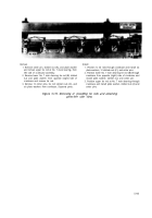
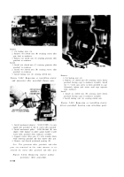
1. Cut locking wire and remove 24 slotted nuts (A) and
12 plate washers attaching main bearing caps, numbers
1, 2, 3, 5,6, and 7 to crankcase assembly.
2. Cut locking w ire and remove four slotted nuts (B) and
two plate washers attaching main thrust bearing cap
(No. 4 or center) to crankcase assembly.
Install
Note.
Do not install locking wire until bearing
cap nuts have been torque tightened (para 7-5c).
1. Apply antiseize compound (FSN 9150-663-1770) and
install two plate washers and four slotted nuts (B)
securing main thrust bearing cap (No. 4) to crankcase
assembly.
2. Apply antiseize compound (FSN 9150-663-1770) and
install 12 plate washers and 24 slotted nuts (A)
securing main bearing caps, numbers 1, 2, 3, 5, 6, and 7
to crankcase assembly.
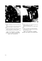
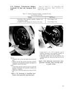
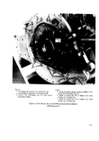
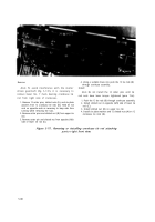
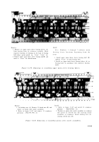
Figure 5-173. Removing or installing main bearing attaching parts.
5-100
Back to Top

