TM-9-2815-200-35
ENGINE, WITH CONTAINER:TURBOSUPERCHARGED, DIESEL ,FUEL INJECTION ,90-DEGREE “V” TYPE, AIR - COOLED ,12 - CYLINDER , ASSEMBLY ;MODELS AVDS-1790-2M (2815-856-4996), AVDS-1790-2A AND AVDS-1790-2AM (2815-856-9005)
TECHNICAL MANUAL; DIRECT SUPPORT, GENERAL SUPPORT AND DEPOT MAINTENANCE MANUAL INCLUDING REPAIR PARTS AND SPECIAL TOOLS LISTS
TM-9-2815-200-35 - Page 440 of 779
Note.
Before removing bolts and self-locking
nuts securing the components of the advance
assembly, check alinement and legibility o f
scribe marks on adjusting ring boss, flyweight,
and drive gearshaft flange. The marks must be
alined to insure proper assembly. If the scribe
marks are not alined, scribe a new line on the
gearshaft flange in alinement with the ring boss
scribe line. Identify the new line using a prick
punch dot or some other method. The new gear
flange mark and ring boss must be in alinement
for proper assembly.
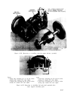
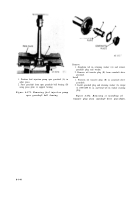
1. Remove intermediate bearing support (A).
2. Remove eight cotter pins, slotted nuts (B) and two flat
washers.
3. Remove six bolts (C).
Figure 6-175. Removing advance flyweight
adjusting ring and injection pump drive
gearshaft attaching parts (adjusting ring
secured with nuts and washers).
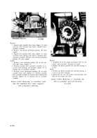
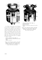
1. Remove intermediate bearing support (A).
2. Cut locking wire (B).
3. Remove six bolts (C).
4. Remove two cotter pins, slotted nuts (D), and flat
washers.
Figure 6-176. Removing advance flyweight
adjusting ring and injection pump drive
gearshaft attaching parts (adjusting
ring secured with bolts).
6-146
Back to Top


