TM-9-2815-205-24 - Page 140 of 856
REMOVAL
1.
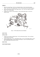
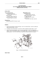
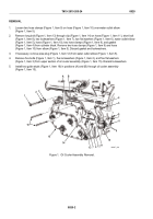
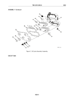
Loosen two hose clamps (Figure 1, Item 9) on hose (Figure 1, Item 10) over water outlet elbow
(Figure 1, Item 5).
2.
Remove long bolt (Figure 1, Item 13) through clip (Figure 1, Item 14) on hose (Figure 1, Item 11), short bolt
(Figure 1, Item 8), two lockwashers (Figure 1, Item 7), two flat washers (Figure 1, Item 6), water outlet elbow
(Figure 1, Item 5), hose (Figure 1, Item 10), two hose clamps (Figure 1, Item 9), and gasket
(Figure 1, Item 4) from cylinder block. Remove two hose clamps (Figure 1, Item 9) and hose
(Figure 1, Item 10) from elbow (Figure 1, Item 5). Discard gasket and lockwashers.
3.
If necessary, remove pipe plug (Figure 1, Item 12) from water outlet elbow (Figure 1, Item 5).
4.
Remove five bolts (Figure 1, Item 1), five lockwashers (Figure 1, Item 2), and five flat washers
(Figure 1, Item 3) from upper section of oil cooler assembly (Figure 1, Item 15). Discard lockwashers.
5.
Install two guide studs (Figure 1, Item 16) in positions (A) and (B) through oil cooler assembly
(Figure 1, Item 15).
1
2
3
4
5
6
7
8
9
10
12
7
13
14
15
11
6
16
A
B
MAINT_049
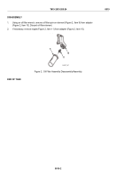
Figure 1.
Oil Cooler Assembly Removal.
TM 9-2815-205-24
0020
0020-2
Back to Top

