TM-9-2815-205-24 - Page 130 of 856
REMOVAL
1.
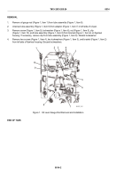
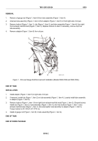
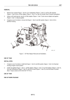
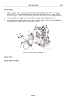
Remove four screws (Figure 1, Item 4), four lockwashers (Figure 1, Item 5), and four flat washers
(Figure 1, Item 6) from oil filter adaptor (Figure 1, Item 7) on rear left cylinder block. Discard lockwashers.
2.
Using a soft head hammer, tap the oil filter adaptor (Figure 1, Item 7) and remove adaptor and gasket
(Figure 1, Item 1). Discard gasket.
3.
If engine is out of container, remove bolt (Figure 1, Item 3) and flat washer (Figure 1, Item 2) from
flywheel housing.
1
2
3
7
4
5
6
MAINT_044
Figure 1.
Oil Filter Adaptor Removal and Installation.
END OF TASK
INSTALLATION
1.
If engine is out of container, install bolt (Figure 1, Item 3) and flat washer (Figure 1, Item 2) in flywheel
housing at eight o'clock position.
2.
Install new gasket (Figure 1, Item 1), oil filter adaptor (Figure 1, Item 7), four flat washers (Figure 1, Item 6),
four new lockwashers (Figure 1, Item 5), and four screws (Figure 1, Item 4) on rear left side of cylinder
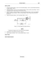
block. Torque screws to 30–35 lb-ft (41–47 N·m).
END OF TASK
END OF WORK PACKAGE
TM 9-2815-205-24
0017
0017-2
Back to Top

