TM-9-2815-205-24 - Page 274 of 856
INSTALLATION - Continued
13.
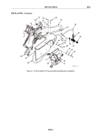
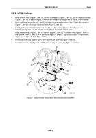
If removed, install elbow (Figure 7, Item 22) in outlet port and adapter (Figure 7, Item 21) in inlet port of
solenoid valve (Figure 7, Item 19). Install elbow (Figure 7, Item 1) in adapter.
14.
Install solenoid valve (Figure 7, Item 19), two new lockwashers (Figure 7, Item 17), and two machine screws
(Figure 7, Item 16) on mounting bracket (Figure 7, Item 18) with fuel inlet facing right side of engine.
Tighten screws.
15.
Loosely install mounting bracket (Figure 7, Item 18), two new lockwashers (Figure 7, Item 14), and two
machine screws (Figure 7, Item 15) on engine bracket (Figure 7, Item 13).
16.
Connect harness assembly (Figure 7, Item 20) to solenoid valve (Figure 7, Item 19) and ignition coil
(Figure 7, Item 30).
17.
Install two leads of harness assembly (Figure 6, Item 20) and two nuts (Figure 6, Items 43 and 44) on air
pump (Figure 6, Item 26).
18.
Connect tube assembly (Figure 7, Item 3) to elbow (Figure 7, Item 22), in solenoid valve (Figure 7, Item 19),
and to elbow (Figure 7, Item 12), in air box heater (Figure 7, Item 11). Tighten connections and two machine
screws (Figure 7, Item 15).
19.
Connect hose assembly (Figure 7, Item 2) to elbow (Figure 7, Item 1) in solenoid valve (Figure 7, Item 19)
and tee (Figure 7, Item 5) to fuel spill tube (Figure 7, Item 4). Tighten connections.
20.
Install loop clamp (Figure 7, Item 7), flat washer (Figure 7, Item 8), new lockwasher (Figure 7, Item 9), and
screw (Figure 7, Item 10) in lower front cover (Figure 7, Item 6). Torque screw to 30–35 lb-ft (41–47 N·m).
3
4
7
1
11
12
13
14
15
16
17
18
19
22
20
21
2
8
9
10
5
2
6
MAINT_121
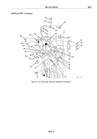
Figure 7.
Air Box Heater Hardware Installation, Continued.
END OF TASK
END OF WORK PACKAGE
TM 9-2815-205-24
0043
0043-12
Back to Top

