TM-9-2815-205-24 - Page 270 of 856
INSTALLATION
1.
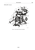
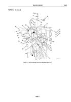
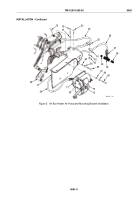
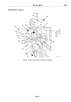
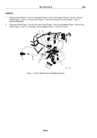
Lay harness assembly (Figure 6, Item 20) in position on front of engine.
2.
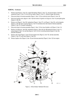
Place angle bracket (Figure 5, Item 27) over front of air inlet housing (Figure 5, Item 72) and against upper
front cover (Figure 5, Item 32). Install two new lockwashers (Figure 5, Item 51) and two long screws
(Figure 5, Item 52) in top of bracket and install two flat washers (Figure 5, Item 64), two new lockwashers
(Figure 5, Item 65), and two short screws (Figure 5, Item 66) in front of bracket. Torque screws
(Figure 5, Item 52) to 16–20 lb-ft (22–27 N·m) and screws (Figure 5, Item 66) to 46–50 lb-ft (62–68 N·m).
NOTE
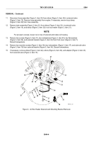
To torque screws (Figure 5, Item 69), it is necessary to loosen center bolt
(Figure 5, Item 73) on bracket assembly (Figure 5, Item 71) and move air pump
(Figure 6, Item 15) and ignition coil (Figure 6, Item 14). Torque center bolt to 60–96 lb-in
(7–11 N·m).
3.
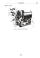
Install bracket assembly (Figure 5, Item 71), four flat washers (Figure 5, Item 67), four new lockwashers
(Figure 5, Item 68), and four screws (Figure 5, Item 69) on angle bracket (Figure 5, Item 27). Torque bolts to
30–35 lb-ft (41–47 N·m).
4.
If removed, install loop clamp (Figure 5, Item 61), connector (Figure 5, Item 57), tee (Figure 5, Item 59), pipe
nipple (Figure 5, Item 58), and pipe plug (Figure 5, Item 60) on air inlet hose (Figure 5, Item 56). Connect
hose to elbow (Figure 5, Item 70) in air pump (Figure 5, Item 26). Tighten connection.
5.
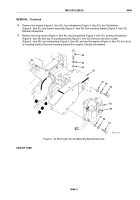
Install two screws (Figure 5, Item 53), two loop clamps (Figure 5, Item 55) on top of bracket, loop clamp
(Figure 5, Item 61) on bottom of bracket, two new lockwashers (Figure 5, Item 62), and two nuts
(Figure 5, Item 63) on angle bracket (Figure 5, Item 27). Torque screws to 30–35 lb-ft (41–47 N·m).
TM 9-2815-205-24
0043
0043-8
Back to Top

