TM-9-2815-205-24 - Page 260 of 856
INSTALLATION - Continued
9.
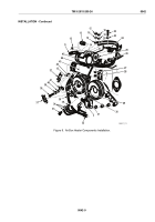
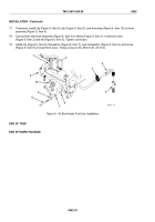
Wind wire wrap (Figure 8, Item 37) around ignition coil cable (Figure 8, Item 13), air hose
(Figure 8, Item 12), and harness assembly (Figure 8, Item 36). If removed, install clip (Figure 8, Item 41) on
air hose (Figure 8, Item 12).
NOTE
Position wiring harness and hose assembly around engine components and brackets
as shown.
10.
If removed, install adapter (Figure 8, Item 42) into hose assembly (Figure 8, Item 12). Connect hose
assembly to check valve (Figure 8, Item 11) and adapter end to elbow (Figure 8, Item 31) at air box heater
body (Figure 8, Item 30). Tighten connections.
11.
Install connector (Figure 8, Item 32) in solenoid (Figure 8, Item 2) and connector (Figure 8, Item 26) in
ignition coil (Figure 8, Item 25).
12.
Install wiring harness lead (Figure 8, Item 15), new lockwasher (Figure 8, Item 16), and nut
(Figure 8, Item 18) on terminal (Figure 8, Item 14). Install lead (Figure 8, Item 20), new lockwasher
(Figure 8, Item 19), and nut (Figure 8, Item 18) on terminal (Figure 8, Item 21) on air pump
(Figure 8, Item 45). Tighten nuts securely.
13.
Install ground wires (Figure 8, Item 34), new copper flat washer (Figure 8, Item 35), and bolt
(Figure 8, Item 33) on air box heater body (Figure 8, Item 30). Torque bolt to 13–17 lb-ft (18–23 N·m).
14.
Install clip (Figure 8, Item 41), on air hose (Figure 8, Item 12), flat washer (Figure 8, Item 40), new
lockwasher (Figure 8, Item 39), and screw (Figure 8, Item 38) on upper front cover. Torque screw to
30–35 lb-ft (41–47 N·m).
15.
Connect boot end of ignition coil cable (Figure 8, Item 13) to igniter (Figure 8, Item 29) and connector end of
ignition coil cable to ignition coil (Figure 8, Item 25).
16.
Install screw (Figure 8, Item 22), flat washer (Figure 8, Item 23), new lockwasher (Figure 8, Item 27), and
nut (Figure 8, Item 28) in bracket (Figure 8, Item 44) and support (Figure 8, Item 43). Torque nut to
30–35 lb-ft (41–47 N·m).
TM 9-2815-205-24
0042
0042-8
Back to Top

