TM-9-2815-205-24 - Page 259 of 856
INSTALLATION - Continued
5.
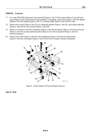
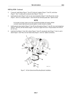
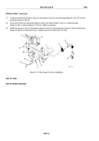
If removed, install elbow (Figure 7, Item 47) (inlet port), adapter (Figure 7, Item 55), and elbow
(Figure 7, Item 1) (outlet port) to solenoid valve (Figure 7, Item 2).
6.
Install solenoid valve (Figure 7, Item 2), two new lockwashers (Figure 7, Item 56) and two screws
(Figure 7, Item 51) on bracket (Figure 7, Item 49) with fuel inlet facing right side. Tighten screws.
NOTE
For access to screws, loosen nut on top of solenoid and rotate coil housing. Rotate
connector toward right side and securely tighten nut after bracket is installed.
7.
Install solenoid valve bracket (Figure 7, Item 49), two flat washers (Figure 7, Item 52), two new lockwashers
(Figure 7, Item 53), and two screws (Figure 7, Item 54) on upper front cover. Torque screws to 30–35 lb-ft
(41–47 N·m).
8.
Install fuel line (Figure 7, Item 46) in elbow (Figure 7, Item 47), at solenoid valve (Figure 7, Item 2), and in
elbow (Figure 7, Item 48) on air box heater body (Figure 7, Item 30). Tighten connections.
47
48
49
51
52
53
54
55
1
50
2
46
MAINT_108
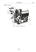
Figure 7.
Air Box Solenoid and Mounting Bracket Installation.
TM 9-2815-205-24
0042
0042-7
Back to Top

