TM-9-2815-205-24 - Page 264 of 856
REMOVAL
1.
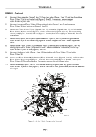
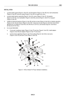
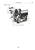
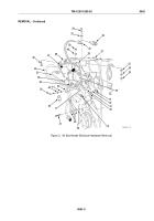
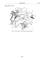
Remove screw (Figure 1, Item 10), lockwasher (Figure 1, Item 9), flat washer (Figure 1, Item 8), and loop
clamp (Figure 1, Item 7) on lower front cover (Figure 1, Item 6). Discard lockwasher.
2.
Disconnect hose assembly (Figure 1, Item 2) from elbow (Figure 1, Item 1) in solenoid valve
(Figure 1, Item 19).
3.
Disconnect hose assembly (Figure 1, Item 2) from tee (Figure 1, Item 5). Disconnect tee from fuel spill tube
(Figure 1, Item 4).
4.
Disconnect harness assembly (Figure 1, Item 20) from fuel solenoid valve (Figure 1, Item 19).
5.
Disconnect tube assembly (Figure 1, Item 3) from elbow (Figure 1, Item 22) in solenoid valve
(Figure 1, Item 19) and from elbow (Figure 1, Item 12) in air box heater (Figure 1, Item 11).
6.
Remove two machine screws (Figure 1, Item 15), two lockwashers (Figure 1, Item 14), and mounting
bracket (Figure 1, Item 18) from engine bracket (Figure 1, Item 13). Discard lockwashers.
7.
Remove two machine screws (Figure 1, Item 16), two lockwashers (Figure 1, Item 17), and solenoid valve
(Figure 1, Item 19) from mounting bracket (Figure 1, Item 18). Discard lockwashers.
8.
If necessary, remove elbow (Figure 1, Item 1), elbow (Figure 1, Item 22), and adapter (Figure 1, Item 21)
from solenoid valve (Figure 1, Item 19).
TM 9-2815-205-24
0043
0043-2
Back to Top

