TM-9-2815-205-24 - Page 268 of 856
REMOVAL - Continued
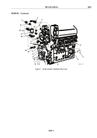
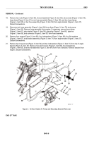
18.
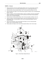
Remove two nuts (Figure 3, Item 63), two lockwashers (Figure 3, Item 62), two screws (Figure 3, Item 53),
loop clamp (Figure 3, Item 61) on air hose assembly (Figure 3, Item 56), and two loop clamps
(Figure 3, Item 55) on fuel hose assembly (Figure 3, Item 54) from angle bracket (Figure 3, Item 27).
Discard lockwashers.
19.
Disconnect air hose assembly (Figure 3, Item 56) from elbow (Figure 3, Item 70) at air pump
(Figure 3, Item 26). Remove hose assembly from engine. If necessary, remove loop clamp
(Figure 3, Item 61), pipe nipple (Figure 3, Item 58), pipe plug (Figure 3, Item 60), pipe tee
(Figure 3, Item 59), and connector (Figure 3, Item 57) from hose assembly.
20.
Remove four screws (Figure 3, Item 69), four lockwashers (Figure 3, Item 68), four flat washers
(Figure 3, Item 67), and bracket assembly (Figure 3, Item 71) from angle bracket (Figure 3, Item 27).
Discard lockwashers.
21.
Remove two long screws (Figure 3, Item 52) and two lockwashers (Figure 3, Item 51) from top of angle
bracket (Figure 3, Item 27). Remove two short screws (Figure 3, Item 66), two lockwashers
(Figure 3, Item 65), and two flat washers (Figure 3, Item 64) from front of bracket. Remove bracket from
engine. Discard lockwashers.
62
63
64
65
66
67
68
61
69
70
57
56
55
54
53
52
51
60
59
58
27
26
56
71
MAINT_117
Figure 3.
Air Box Heater Air Pump and Mounting Bracket Removal.
END OF TASK
TM 9-2815-205-24
0043
0043-6
Back to Top

