TM-9-2815-205-24 - Page 340 of 856
NOTE
This procedure shows one fuel injector on right cylinder head assembly at cylinder #1 and
one fuel injector on left cylinder head assembly at cylinder #2. To remove and install fuel
injectors, other than those shown, adjust task step procedures where indicated.
REMOVAL
1.
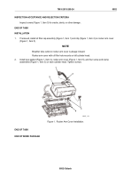
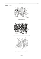
Locate fuel injector (Figure 1, Item 1) to be removed.
1
MAINT_442
Figure 1.
Fuel Injector.
CAUTION
Rotate engine crankshaft in clockwise direction only. Do not rotate crankshaft in
counterclockwise direction using crankshaft bolt. Crankshaft bolt can loosen and
serious engine damage may result if crankshaft bolt is not securely tightened to
crankshaft.
Manually rotating the engine crankshaft could create ignition and start the engine.
When rotating engine crankshaft in clockwise direction, manually hold the fuel
shut-off control lever, located on the governor cover assembly, in the fuel shut-
off/no fuel position. Visually make sure all fuel injector racks are in the no fuel
position.
When the engine crankshaft is being rotated by helper, the mechanic must visually
monitor the positions of fuel injector rocker arm, two exhaust valve rocker arms
and the three related push rods, which are associated to the fuel injector being
removed.
2.
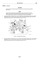
Manually rotate engine crankshaft in clockwise direction until pressure of fuel injector rocker arm
(Figure 2, Item 3) and two exhaust valve rocker arms (Figure 2, Item 2) are released from fuel injector
plunger follower (Figure 3, Item 4) and exhaust valve stems (Figure 3, Item 5). Make sure fuel injector
rocker arm (Figure 4, Item 3) and exhaust valve rocker arms (Figure 4, Item 2) are fully released and three
push rods (Figure 4, Item 6) are loose, in lowest travel position, and horizontally aligned.
TM 9-2815-205-24
0054
0054-2
Back to Top


