TM-9-2815-205-24 - Page 336 of 856
ASSEMBLY - Continued
NOTE
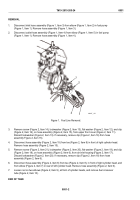
On models 5063-5393 and 5063-539L, outlet from breather housings point
outboard.
On model 5063-5392, right breather housing outlet points towards front of engine
and left breather housing outlet points towards rear of engine.
3.
Install breather retainer (Figure 2, Item 15) and filtering disk (Figure 2, Item 14) in breather housing
(Figure 2, Item 1).
4.
Install new seal (Figure 2, Item 4), breather housing (Figure 2, Item 1), retainer (Figure 2, Item 13), and
three screws (Figure 2, Item 12) in rocker arm cover (Figure 2, Item 9). Torque screws to 48–72 lb-in
(5–8 N·m).
END OF TASK
INSTALLATION
NOTE
Right and left rocker arm covers are identical except for oil filler hole. Use same procedure
to remove both covers.
1.
Install new gasket (Figure 2, Item 11) in groove at bottom of rocker arm cover (Figure 2, Item 9). First press
gasket into corners and then sides.
NOTE
On model 5063-5392, oil filler cap is at rear of right rocker arm cover.
On models 5063-5393 and 5063-539L, oil filler cap is at front of right rocker arm
cover.
2.
Install rocker arm cover (Figure 2, Item 9), two resilient mounts (Figure 2, Item 16), two flat washers
(Figure 2, Item 17), and two bolts (Figure 2, Item 18) on cylinder head. Torque bolts to
96–156 lb-in (11–18 N·m).
3.
On models 5063-5393 and 5063-539L, install hose (Figure 2, Item 3) and clamp (Figure 2, Item 2) on
breather housing (Figure 2, Item 1) with hose pointing downward. Tighten clamp.
TM 9-2815-205-24
0053
0053-4
Back to Top

