TM-9-2815-205-24 - Page 654 of 856
REMOVAL
NOTE
All models have a fuel pump drive assembly on the right side. Only models 5063-5393 and
5063-539L have a hydraulic pump drive assembly on the left side. Repeat the same
procedures on the left side for the hydraulic pump drive assembly replacement.
1.
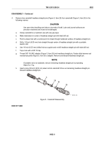
Remove two self-locking bolts (Figure 1, Item 8) and adapter (Figure 1, Item 7) from drive gear
(Figure 1, Item 4). Discard self-locking bolts.
2.
Remove self-locking bolt (Figure 1, Item 6), flat washer (Figure 1, Item 5), two thrust washers
(Figure 1, Item 2), gear (Figure 1, Item 4), and hub (Figure 1, Item 3) from end plate. Discard self-locking
bolt.
1
2
3
4
2
5
6
7
8
6
8
7
5
2
4
3
2
1
MAINT_339
Figure 1.
Fuel Pump Drive Removal/Installation.
END OF TASK
CLEANING
WARNING
Compressed air used for cleaning purposes will not exceed 30 PSI (207 kPa). Use only
with protective equipment (goggles, face shield, gloves, etc.). Failure to comply may result
in injury to personnel.
Wash gear, hub, and flat washers in fuel oil and dry with compressed air.
END OF TASK
INSPECTION-ACCEPTANCE AND REJECTION CRITERIA
1.
Inspect thrust washers, hub, and drive gear bearing for wear and scoring.
TM 9-2815-205-24
0091
0091-2
Back to Top


