TM-9-2815-205-24 - Page 646 of 856
REMOVAL
NOTE
To remove camshaft nuts with flywheel housing on engine, secure flywheel or
crankshaft to prevent camshaft gears from turning.
To remove camshaft nuts with flywheel housing removed, wedge a rag between
camshaft gears.
1.
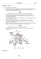
Remove two nuts (Figure 1, Item 1) from front end of camshafts using 100–500 lb-ft torque wrench.
2.
Using two pry bars between pulley (Figure 1, Item 2) and front cover (Figure 1, Item 3), pry two pulleys
off shafts.
NOTE
Several front cover fastening bolts were removed during removal of clips, water
pump idler pulley assembly, solenoid bracket, and fan support bracket.
Quantity and length of bolts vary with engine model. Size and location of bolts for
each model is noted in Table 1 for installation.
3.
Remove all bolts (Figure 1, Item 6), lockwashers (Figure 1, Item 5), and flat washers (Figure 1, Item 4)
fastening upper front cover (Figure 1, Item 3) to cylinder block. Discard lockwashers.
4.
Using soft head hammer, tap front cover (Figure 1, Item 3) away from cylinder block. Remove front cover
and gasket (Figure 1, Item 9). Discard gasket.
5.
Remove two Woodruff keys (Figure 1, Item 7) and two oil seal spacers (Figure 1, Item 8) from camshafts.
1
2
3
6
5
4
8
9
7
2
1
MAINT_333
Figure 1.
Upper Front Cover Removal.
END OF TASK
TM 9-2815-205-24
0090
0090-2
Back to Top

