TM-9-2815-205-24 - Page 636 of 856
DISASSEMBLY - Continued
2.
Front cover assembly removal procedures:
a.
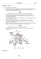
Remove plug (Figure 3, Item 33), plug (Figure 3, Item 24), two copper flat washers (Figure 3, Item 23),
two springs (Figure 3, Item 22), and two sleeves (Figure 3, Item 25) from sides of front cover
(Figure 3, Item 10). Discard copper flat washers.
NOTE
Model 5063-5299 does not use cover plate (Figure 3, Item 28) or fastening hardware.
b.
Remove two screws (Figure 3, Item 26), two lockwashers (Figure 3, Item 27), cover plate
(Figure 3, Item 28), and gasket (Figure 3, Item 29) from bottom of front cover (Figure 3, Item 10).
Discard gasket and lockwashers.
c.
For model 5063-5299: if necessary, remove two plugs (Figure 3, Item 19) and plug (Figure 3, Item 32)
from front cover (Figure 3, Item 10).
d.
For all except model 5063-5299: if necessary, remove four plugs (Figure 3, Item 19), plug
(Figure 3, Item 32), plug (Figure 3, Item 20), and cup plug (Figure 3, Item 21) from front cover
(Figure 3, Item 10). Discard cup plug.
e.
Drill two holes in opposite sides of casing of oil seal (Figure 3, Item 30). Thread metal screws with flat
washers into casing. Pry against flat washers and remove oil seal. Discard seal.
NOTE
Model 5063-5299 does not use sleeve bearing (Figure 3, Item 31).
f.
Press or drive sleeve bearing (Figure 3, Item 31) from bore in front cover (Figure 3, Item 10).
Discard bearing.
33
PLUG MARKED "R"
PLUG MARKED "X"
23
22
19
22
23
24
25
25
32
10
31
21
30
19
20
26
27
28
29
MAINT_327
Figure 3.
Front Cover Disassembly.
END OF TASK
TM 9-2815-205-24
0089
0089-4
Back to Top


