TM-9-2815-205-24 - Page 642 of 856
INSTALLATION - Continued
7.
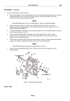
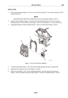
Remove guide studs (Figure 8, Item 36) and rotate front cover (Figure 8, Item 10) slightly to engage teeth,
then align cover with dowel pins (Figure 8, Item 37) on cylinder block and slide cover up against
gasket (Figure 8, Item 4).
NOTE
On models 5063-5393 and 5063-539L, do not install four screws
(Figure 8, Item 13) because of front support installation.
On 5063-5299, 5063-5393, do not install screw (Figure 8, Item 11) at location
(Figure 8, Item A) because of fuel line clip installation.
8.
Install 12 flat washers (Figure 8, Item 3), 12 new lockwashers (Figure 8, Item 2), four long screws
(Figure 8, Item 13), four mid-sized screws (Figure 8, Item 11), and four short screws (Figure 8, Item 1) on
front cover (Figure 8, Item 10).
9.
Install spacer ring (Figure 8, Item 12) on crankshaft (Figure 8, Item 6) with bevel toward cylinder block and
push spacer ring into oil seal (Figure 8, Item 30).
10.
Torque front cover screws (Figure 8, Item 13, 11, and 1) to 30–35 lb-ft (41–47 N·m).
11.
Trim excess material from gasket (Figure 8, Item 4) level to cylinder block.
1
3
2
13
12
16
30
2
3
36
3
10
A
36
37
2
11
6
38
4
MAINT_332
Figure 8.
Front Cover Installation.
END OF TASK
FOLLOW ON TASK
1.
Install engine front support (model 5063-5392) (WP 0069).
2.
Install engine front support (model 5063-5299) (WP 0068).
3.
Install crankshaft hub or pulley (models 5063-5392) (WP 0067).
TM 9-2815-205-24
0089
0089-10
Back to Top


