TM-9-2815-205-24 - Page 641 of 856
INSTALLATION
1.
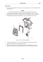
Place oil pump assembly (Figure 7, Item 9) in rear of front cover (Figure 7, Item 10) with markings “UP R.H."
at top of front cover.
NOTE
Models 5063-5392, 5063-5393, and 5063-539L do not use lockwashers (Figure 7, Item 8).
2.
Install six new lockwashers (Figure 7, Item 8) and six self-locking bolts (Figure 7, Item 7) in oil pump
assembly (Figure 7, Item 9) and front cover (Figure 7, Item 10). Torque bolts to 13–17 lb-ft (18–23 N·m).
3.
Using gasket adhesive, install new gasket (Figure 7, Item 4) on cylinder block (Figure 7, Item 5).
5
4
10
9
8
7
MAINT_331
Figure 7.
Front Cover Oil Pump Installation.
4.
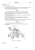
Thread two guide studs (Figure 7, Item 36) into diametrically opposite bolt holes in cylinder block.
5.
Apply light coat of grease to lip of oil seal (Figure 7, Item 30).
6.
Slide front cover (Figure 7, Item 10) over guide studs (Figure 7, Item 36) until inner oil pump rotor
(Figure 7, Item 16) contacts oil pump drive gear (Figure 7, Item 38) on crankshaft (Figure 7, Item 6).
TM 9-2815-205-24
0089
0089-9
Back to Top


