TM-9-2815-205-24 - Page 650 of 856
INSTALLATION - Continued
NOTE
Several front cover fastening bolts are installed with installation of clips, water pump idler
pulley assembly, solenoid bracket, and fan support bracket (WP 0042) , (WP 0043) ,
(WP 0044) , (WP 0046) , and (WP 0069). See Table 1 for bolt sizes and locations.
2.
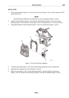
Install upper front cover (Figure 5, Item 3), flat washers (Figure 5, Item 4), new lockwashers
(Figure 5, Item 5), and bolts (Figure 5, Item 6) on cylinder block. Torque bolts to 30–35 lb-ft (41–47 N·m).
3.
Apply grease to outside diameter of two seal spacers (Figure 5, Item 8) and slide in position on camshafts.
4.
Install two Woodruff keys (Figure 5, Item 7) in slot at end of camshafts.
5.
Align keyway in pulley with Woodruff key (Figure 5, Item 7). Slide two pulleys (Figure 5, Item 2) on ends
of camshafts.
NOTE
To tighten and torque camshaft nuts with flywheel housing on engine, secure
flywheel or crankshaft to prevent camshaft gears from turning.
To tighten and torque camshaft nuts with flywheel housing removed, wedge a rag
between camshaft gears.
6.
Install two nuts (Figure 5, Item 1) on camshafts and torque to 300–325 lb-ft (407–441 N·m).
8
8
3
1
1
2
7
7
2
6
5
4
MAINT_337
Figure 5.
Upper Cam Shaft Pulley Installation.
TM 9-2815-205-24
0090
0090-6
Back to Top


