TM-9-2815-205-24 - Page 659 of 856
REMOVAL - Continued
5.
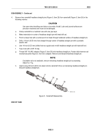
Remove two screws (Figure 2, Item 15), two lockwashers (Figure 2, Item 16), and retaining plate
(Figure 2, Item 17) from each camshaft gear (Figure 2, Item 13). Discard lockwashers.
6.
Wedge a rag between two camshaft gears (Figure 2, Item 13). Remove two nuts (Figure 2, Item 14).
7.
Remove rag from camshaft gears (Figure 2, Item 13).
8.
Remove four self-locking bolts (Figure 2, Item 11) fastening two spacer plates (Figure 2, Item 18) to cylinder
block. Insert socket wrench through opening in web of camshaft gear (Figure 2, Item 13) to gain access to
bolts. Discard self-locking bolts.
9.
Remove camshaft and gear assemblies (Figure 2, Item 12) from rear of cylinder block.
11
12
13
14
15
16
17
13
18
MAINT_341
Figure 2.
Cam and Idler Gear Removal.
END OF TASK
TM 9-2815-205-24
0092
0092-3
Back to Top


