TM-9-2815-205-24 - Page 668 of 856
INSTALLATION - Continued
6.
Remove rag from between camshaft gears.
7.
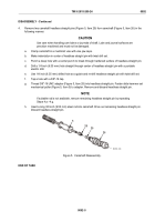
Place inner idler gear thrust washer (Figure 12, Item 10) on front of gear hub (Figure 12, Item 8) with oil
grooves in thrust washer facing idler gear and with flat in thrust washer over flat on gear hub.
8.
Insert small end of gear hub (Figure 12, Item 8) into counterbore of cylinder block.
9.
Thread two large pilot screws (Figure 12, Item 37) and small pilot screw (Figure 12, Item 38) through gear
hub (Figure 12, Item 8) and into cylinder block.
10.
Install screw (Figure 12, Item 6) in center hole in gear hub (Figure 12, Item 8). Torque bolt
to 40–45 lb-ft (54–61 N·m). Remove two large pilot screws (Figure 12, Item 37) and small pilot screw
(Figure 12, Item 38) from gear hub.
11.
Lubricate gear hub (Figure 12, Item 8), idler gear bearing (Figure 12, Item 24), and inner thrust washer
(Figure 12, Item 10) with engine oil.
12.
Slide idler gear assembly (Figure 12, Item 9) over gear hub (Figure 12, Item 8). Align triangles inside circles
on idler gear with triangles on camshaft gear and on crankshaft gear as shown in timing diagram.
13.
Lightly apply grease to grooved face of thrust washer (Figure 12, Item 7). Place thrust washer over gear hub
(Figure 12, Item 8) with grooved face toward idler gear and flat in thrust washer over flat of gear hub.
NOTE
Fit between dirt deflector and tachometer drive shaft must be sufficiently snug to require
some degree of force to move dirt deflector. If necessary, use sealing compound, ASTM
D5363, between parts to correct fit.
14.
If removed, install tachometer dirt deflector (Figure 12, Item 2) on tachometer drive shaft (Figure 12, Item 1).
15.
Using a sleeve (Figure 12, Item 36), tap tachometer drive assembly (Figure 12, Item 3) into rear of left
camshaft.
10
8
38
6
7
9
37
36
3
2
1
MODELS
5063-5299
5063-5393
5063-539L
24
MAINT_350
Figure 12.
Cam and Idler Gear Hardware Installation.
TM 9-2815-205-24
0092
0092-12
Back to Top


