TM-9-2815-205-24 - Page 664 of 856
ASSEMBLY
NOTE
Use same procedure for left and right camshaft.
1.
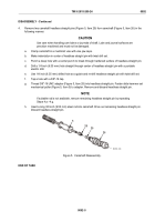
Coat new headless straight pins (Figure 8, Item 29) with sealing compound and press into ends of camshaft
(Figure 8, Item 26) to a depth of 1.940 inches (49.28 mm).
CAUTION
Camshafts improperly installed may cause severe engine damage.
NOTE
Camshafts are stamped at ends for location. Camshaft marked “RH-R BANK" goes in right
side, and camshaft marked “RH-L BANK" goes in left side. Install camshafts with markings
at rear of engine.
2.
Install spacer sleeve (Figure 8, Item 27) and Woodruff key (Figure 8, Item 23) to rear of
camshaft (Figure 8, Item 26).
3.
Lubricate spacer plate (Figure 8, Item 18) with engine oil and place over spacer sleeve (Figure 8, Item 27).
1.940 in.
(49.28 mm)
23
26
27
18
26
29
MAINT_346
Figure 8.
Camshaft Assembly.
TM 9-2815-205-24
0092
0092-8
Back to Top


