TM-9-2815-205-24 - Page 667 of 856
INSTALLATION
1.
Lubricate camshaft bearings and journals with engine oil and slide camshaft and gear assemblies
(Figure 11, Item 12) into cylinder block.
2.
Align timing marks (triangles) on camshaft gears (Figure 11, Item 13) as shown in timing diagram.
3.
Install four new self-locking bolts (Figure 11, Item 11) through two spacer plates (Figure 11, Item 18) and
into cylinder block. Rotate camshaft gears to gain access to bolt holes. Torque bolts
to 30–35 lb-ft (41–47 N·m).
4.
Place a rag between teeth of two camshaft gears. Torque camshaft nuts (Figure 11, Item 14)
to 300–325 lb-ft (407–441 N·m).
5.
Install retainer plate (Figure 11, Item 17), two new lockwashers (Figure 11, Item 16), and two screws
(Figure 11, Item 15) on each camshaft gear (Figure 11, Item 13). Torque screws to 35–39 lb-ft (47–53 N·m).
15
16
17
12
13
13
11
13
18
14
TIMING
DIAGRAM
MAINT_349
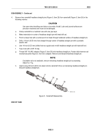
Figure 11.
Cam and Idler Gear Installation.
TM 9-2815-205-24
0092
0092-11
Back to Top


