TM-9-2815-210-34-2-2 - Page 597 of 968
TM 9-2815-210-34-2-2
FRAME 2
1.
2.
3.
4.
5.
6.
7.
8.
9.
WARNING
Smoking, sparks or open flames are not allowed within 50
feet of work area during this task. Fire or explosion
could occur, causing injury to personnel and damage to
equipment.
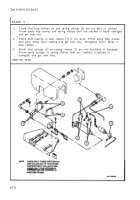
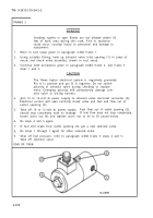
Refer to test setup given in paragraph 4-68d frame 1.
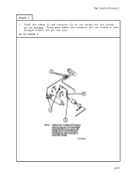
Using suitable fitting, hook up solenoid valve inlet opening (1) in place of
nozzle and check valve assembly, shown in test setup.
Continue with procedures given in paragraph 4-68d frame 2, and frame 3
steps 1 and 2.
CAUTION
The flame heater electrical system is negatively grounded.
Pin A is positive and pin B is negative. Do not switch
polarity of solenoid valve during checking or replace-
ment. Changing polarity will permanently damage sole-
noid valve or wiring harness.
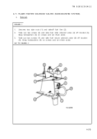
Join 10 to 12-volt dc power supply to solenoid valve electrical connector (2).
Electrical current will open normally closed valve and fuel will flow out of
outlet opening (3).
Take off 10 to 12-volt dc power supply.
Fuel flow out of outlet opening (3)
should stop completely with no leakage.
If fuel flow does not stop completely,
loosen acorn nut (4) and tighten acorn nut to 40 to 50 pound-inches.
Do steps 4 and 5 again.
If fuel still leaks from outlet opening (3), get a new solenoid valve.
Do steps 1 through 7 again for other solenoid valve.
Shut off fuel pressure, refer to paragraph 4-68d frame 3 steps 4 and 5.
Take off solenoid valve.
END OF TASK
4-578
Back to Top

